Integrating Visual Positioning UV Printers with CAD/CAM
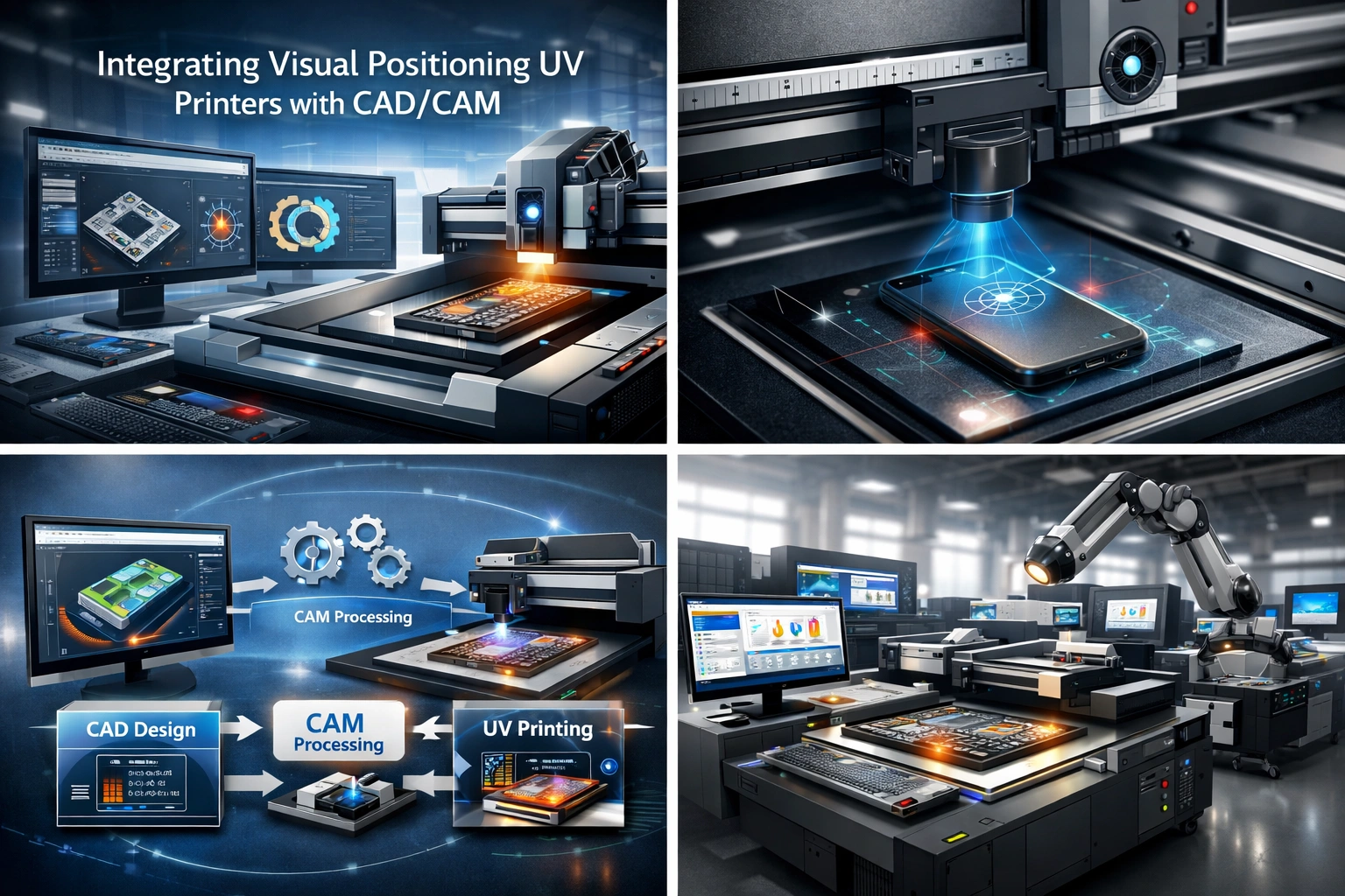
The digital manufacturing and printing industries are evolving at an unprecedented pace. As customer demand shifts toward customization, faster turnaround times, and higher accuracy, businesses must adopt smarter and more connected production workflows. One of the most impactful advancements in this space is the integration of Visual Positioning UV printers with CAD/CAM systems.
Visual Positioning UV printers bring precision printing to irregular, pre-shaped, or pre-printed objects, while CAD/CAM systems streamline the design and manufacturing process through automation and accuracy. When these two technologies work together, they create a seamless digital-to-physical workflow that significantly enhances productivity, reduces waste, and improves output quality.
This article explores how to successfully integrate Visual Positioning UV printers with CAD/CAM systems, the technical considerations involved, workflow optimization strategies, real-world benefits, and best practices to ensure long-term success. Whether you operate a print shop, manufacturing facility, or customization business, this guide will help you build a future-ready production environment.
Understanding Visual Positioning UV Printers
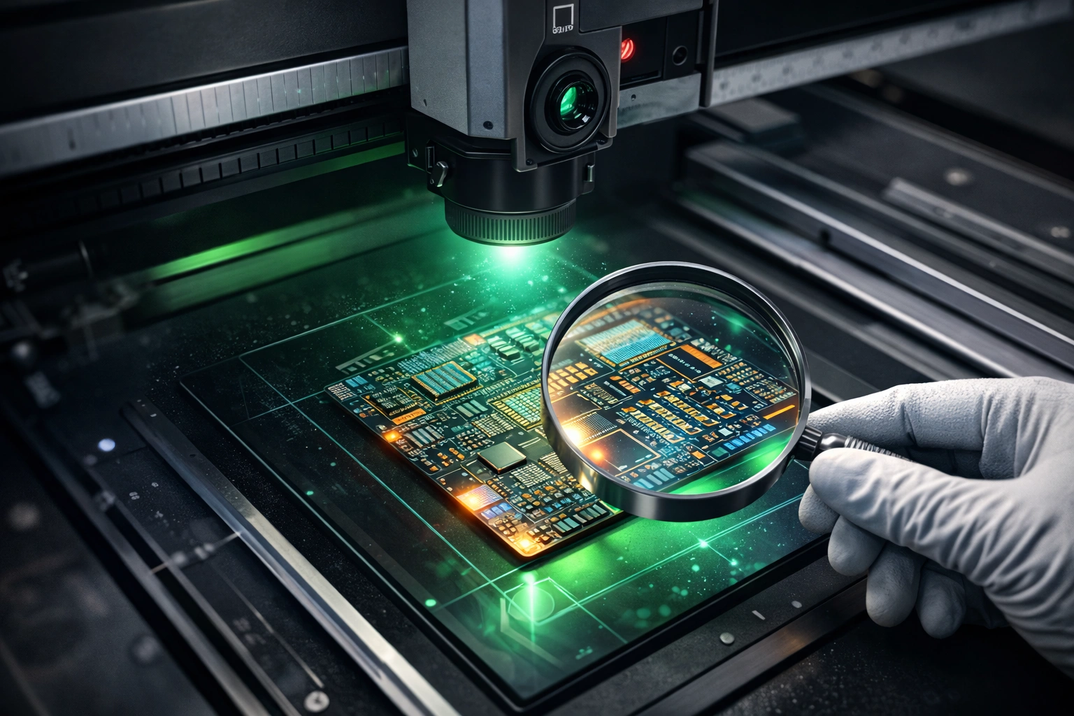
Visual Positioning UV printers are advanced digital printing machines designed to print with extreme accuracy on a wide range of substrates. Unlike conventional UV printers, these systems use camera-based vision technology to detect the exact position, orientation, and contours of the object being printed.
By analyzing real-time visual data, the printer automatically adjusts print placement, ensuring perfect alignment even on non-standard shapes or variable layouts. UV inks are instantly cured using ultraviolet light, allowing printing on materials that traditionally posed challenges for ink adhesion.
Key Characteristics of Visual Positioning UV Printers
Camera-based alignment for precise print placement
Instant UV ink curing, enabling fast production
Support for rigid and irregular substrates
High-resolution output with sharp edges and vibrant colors
Minimal setup time for short or variable runs
This combination makes Visual Positioning UV printers ideal for industries focused on customization, personalization, and short-run production.
Advantages of Visual Positioning UV Printing
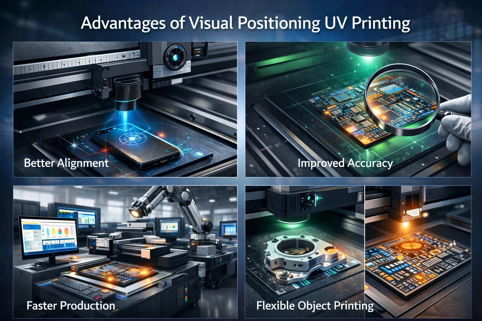
Integrating Visual Positioning UV printing into a modern production workflow offers several measurable benefits.
Material Versatility
These printers can handle materials such as glass, acrylic, metal, wood, leather, plastic, ceramics, and coated fabrics. This flexibility opens opportunities across signage, packaging, industrial parts, promotional products, and décor.
Precision and Consistency
Vision systems eliminate manual alignment errors, ensuring consistent output even across large batches or mixed designs.
Production Speed
UV ink curing happens instantly, removing the need for drying time and enabling faster job completion.
Durability of Prints
UV-cured inks are resistant to moisture, fading, chemicals, and abrasion, making them suitable for both indoor and outdoor applications.
Reduced Waste
Accurate positioning minimizes misprints, saving material costs and improving sustainability.
Overview of CAD/CAM Systems
CAD (Computer-Aided Design) and CAM (Computer-Aided Manufacturing) systems form the digital backbone of modern manufacturing environments.
CAD Systems
CAD software is used to create precise digital designs, technical drawings, and layouts. Designers can control dimensions, shapes, layers, colors, and tolerances with exceptional accuracy.
CAM Systems
CAM software translates CAD designs into machine-readable instructions. These instructions guide machines on how to execute tasks such as cutting, engraving, milling, or printing.
Why CAD/CAM Matters in Printing
When integrated with printing systems, CAD/CAM software ensures that what is designed digitally is produced accurately in the physical world, with minimal interpretation or manual intervention.
Benefits of CAD/CAM Integration
Improved accuracy by eliminating manual data transfer
Faster production cycles through automation
Easy design modifications without restarting workflows
Lower operational costs due to reduced errors
Better scalability for high-volume or customized production
When combined with Visual Positioning UV printers, CAD/CAM systems elevate printing from a standalone process to a fully automated manufacturing solution.
Why Integration Is Essential
Standalone machines and disconnected software systems create inefficiencies, data duplication, and human error. Integration bridges the gap between design and production, creating a single source of truth for every job.
Key reasons integration is critical:
Increasing demand for personalized products
Rising labor costs requiring automation
Need for consistent quality across batches
Pressure to reduce turnaround times
Growing complexity of print layouts and materials
A connected CAD/CAM and UV printing ecosystem ensures that businesses remain competitive and scalable.
Step-by-Step Integration Process
1. Assess Business Requirements
Before integrating systems, evaluate your production needs carefully.
Consider:
Types of products you print
Substrate shapes and sizes
Design complexity
Daily or monthly production volume
Level of customization required
This assessment helps determine the level of integration needed and prevents unnecessary investment.
2. Select Compatible CAD/CAM Software
Not all CAD/CAM platforms are optimized for printing workflows. Choose software that supports:
Vector and raster file formats
Accurate scaling and dimension control
Layer-based design management
Export compatibility with UV printer RIP software
Color profile and ICC support
Software compatibility ensures smooth data flow from design to print.
3. Ensure Printer Software Compatibility
The printer’s control software must be capable of:
Importing CAD-generated files
Interpreting vector paths and print zones
Mapping visual positioning data to design coordinates
Communicating with CAM instructions
In many cases, a RIP (Raster Image Processor) acts as the bridge between CAD/CAM output and the printer hardware.
4. Configure Hardware Communication
Integration requires stable communication between systems.
Key steps include:
Network setup for printer and workstation
Driver installation and firmware configuration
Camera calibration for accurate object detection
Synchronization of coordinate systems
Proper hardware configuration ensures that visual data aligns perfectly with design files.
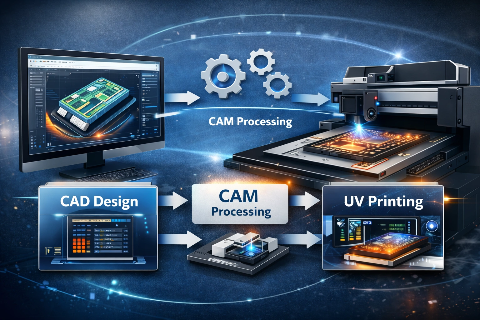
5. Establish a Unified Workflow
A standardized workflow prevents confusion and errors.
Typical workflow:
Design creation in CAD software
Design validation and export
CAM processing and toolpath or print path generation
File transfer to printer software
Vision system alignment and verification
UV printing execution
Quality inspection
Documenting this workflow ensures consistency across teams.
6. Implement Quality Control Checkpoints
Quality assurance should be built into the process.
Monitor:
Print alignment accuracy
Color consistency
Ink adhesion
Substrate positioning
Reprint frequency
Automated checks reduce rework and protect brand reputation.
7. Train Operators and Designers
Even the most advanced system fails without skilled operators.
Training should cover:
CAD design best practices for printing
CAM output optimization
Printer calibration and maintenance
Troubleshooting alignment or file errors
Cross-functional knowledge improves collaboration between design and production teams.
Optimizing Performance After Integration
Integration is not a one-time task; it requires ongoing optimization.
Data-Driven Improvements
Track key metrics such as:
Print accuracy rate
Job completion time
Material waste percentage
Machine downtime
Use these insights to refine workflows and improve efficiency.
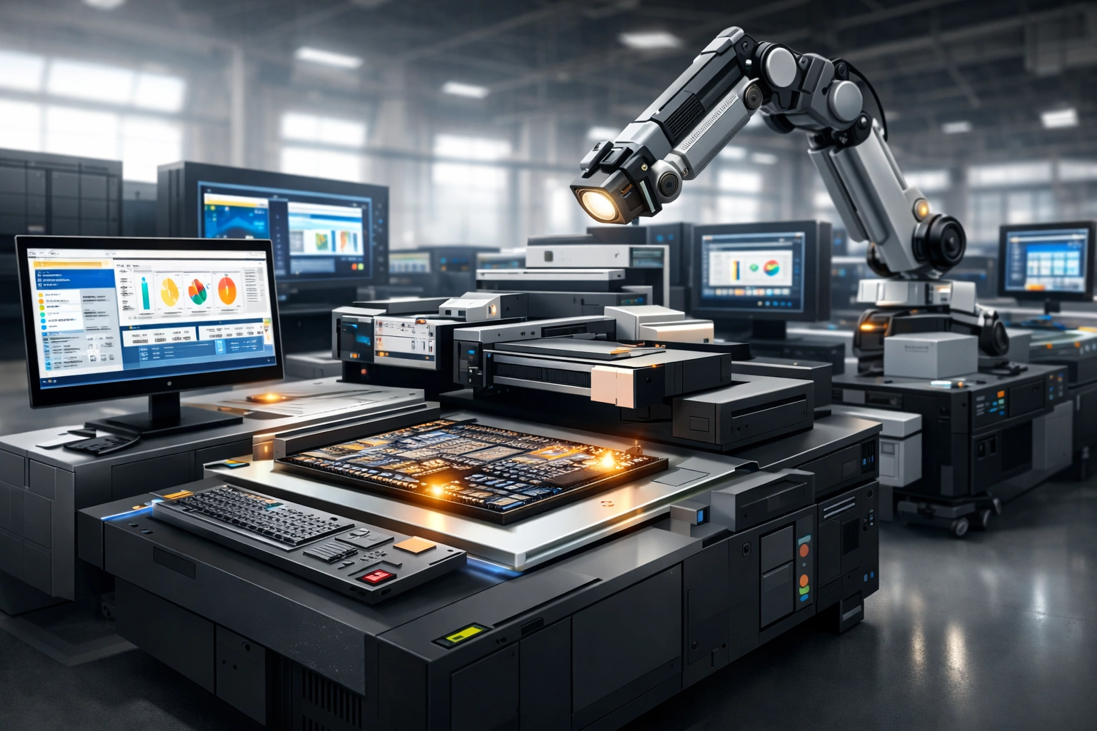
Automation Opportunities
Advanced integrations allow:
Automated job queuing
Batch processing of designs
Variable data printing
Real-time production monitoring
Automation reduces dependency on manual intervention.
Maintenance and Updates
Regularly update:
CAD/CAM software
Printer firmware
Vision system calibration parameters
This ensures compatibility, security, and performance improvements.
Common Challenges and Solutions
File Compatibility Issues
Solution: Standardize file formats and naming conventions across teams.
Alignment Errors
Solution: Regular camera calibration and substrate positioning checks.
Color Inconsistency
Solution: Use calibrated monitors, consistent color profiles, and controlled lighting.
Workflow Bottlenecks
Solution: Analyze data logs and automate repetitive tasks.
Industry Applications
Integrated Visual Positioning UV printing with CAD/CAM systems is widely used in:
Customized packaging
Industrial component marking
Promotional products
Signage and displays
Consumer electronics branding
Interior décor and furniture printing
Each application benefits from accuracy, repeatability, and speed.
Future Trends
The future of CAD/CAM and UV printing integration includes:
AI-assisted design validation
Predictive maintenance using machine data
Cloud-based workflow management
Smart factories with end-to-end automation
Early adopters gain a significant competitive advantage.
Conclusion
Integrating Visual Positioning UV printers with CAD/CAM systems is no longer optional for businesses aiming to stay competitive in modern manufacturing and printing. This integration creates a seamless, accurate, and efficient workflow that bridges design and production while reducing errors, waste, and turnaround time.
By selecting compatible software, configuring hardware correctly, training teams, and continuously optimizing processes, businesses can unlock the full potential of their equipment. The result is higher quality output, improved scalability, and greater customer satisfaction.
A well-executed integration is not just a technical upgrade—it is a strategic investment in long-term growth and operational excellence.
explore our high-quality Visual Positioning UV printers here.
Frequently Asked Questions
What materials work best with Visual Positioning UV printers?
These printers support glass, metal, wood, plastic, acrylic, leather, ceramics, and coated surfaces.
Do CAD/CAM systems require customization for UV printing?
In many cases, yes. Workflow adjustments and software configuration improve compatibility and performance.
Is integration suitable for small businesses?
Absolutely. Even small print shops benefit from reduced waste, faster production, and better consistency.
How long does integration take?
Depending on system complexity, it can range from a few days to several weeks.
Does integration reduce operating costs?
Yes. Automation, accuracy, and reduced reprints significantly lower long-term costs.