

 HOME
 PRODUCT CENTER
 ABOUT US
 DOWNLOAD CENTER
 SUPPORT CENTER
 SUBSCRIBE
 BLOG
Direct UV printing on pre-cut acrylic panels needs to align the holes, slots, curved edges, mounting points, and irregular contours. For manufacturers producing acrylic signs, control panels, display components, and custom enclosures, the challenge is to connect the digital artwork with the actual geometry of each panel.
A reliable workflow combines accurate cutting data, consistent panel positioning, suitable edge margins, and camera-based registration where the printer supports it. These controls help reduce setup errors and improve repeatability across production batches.
Why Pre-Cut Acrylic Panels Require Accurate Registration
Pre-cut acrylic panels are workpieces whose final outlines and functional features have already been created before printing. Unlike printing on a full rectangular sheet, the artwork must fit the actual geometry of each finished part.
A panel may contain mounting holes, rounded corners, narrow borders, slots, or multiple cutouts. These features create reference points that influence where graphics should be printed.
Three types of accuracy matter:
· Cutout alignment: Printed elements must remain correctly positioned relative to holes, slots, and other functional features.
· Edge margin control: Graphics must maintain the required clearance from the panel's outer boundary and internal cutouts.
· Layer registration: When designs use multiple ink layers, such as white ink beneath CMYK, the layers must align with one another.
These requirements are particularly important for illuminated signs, equipment labels, retail displays, and acrylic panels that must fit into a larger assembly.
A panel can look visually attractive but still fail quality inspection if a mounting hole is partially covered or the printed border is inconsistent. Registration should therefore be treated as a dimensional quality requirement, not merely a visual preference.
Prepare Cut Files and Artwork Before Printing
Artwork preparation establishes the relationship between the panel's physical dimensions and the digital design. Before printing, the cutting file and print file should be checked together to prevent mismatched dimensions or reference points.
Start with the original CAD, vector, or manufacturing file whenever possible. Confirm the final panel dimensions, hole centers, slot locations, corner radii, and any features that must remain free of ink.
· A practical preparation checklist includes:
· Confirm that the print artwork and cutting file use the same units and scale.
· Check whether the supplied dimensions refer to the finished panel or the original sheet.
· Identify holes, slots, and edges that must remain unobstructed.
· Confirm the correct orientation of front-facing and reverse-printed designs.
· Define the intended print boundary and any required bleed.
Remove obsolete reference marks that could be mistaken for registration features.
For transparent acrylic, also determine whether the design will be printed on the front or reverse side. Reverse printing changes the artwork orientation and may affect how the camera identifies reference features.
Set Edge Margins Around Outer Edges and Cutouts
An edge margin is the intentional clearance between printed artwork and a physical panel boundary or cutout. Setting this margin helps prevent unwanted ink near edges, incomplete graphics, and conflicts with holes or mounting hardware.
The required margin depends on the panel design, cutting accuracy, positioning method, print requirements, and assembly conditions. There is no single edge-margin value suitable for every acrylic product.
For example, a decorative panel may allow a wider visual border, while a control panel with closely spaced buttons and mounting holes may require tighter dimensional control.
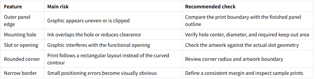
A useful planning approach is to consider the combined effects of cutting tolerance, positioning error, and any additional clearance required by the product design.
If the cut edge can vary from its nominal position, the print position can also vary, and the design has a required minimum clearance, the planned margin must account for these factors. Use the applicable worst-case tolerance stack rather than simply adding an arbitrary border.
For products with critical mounting features, inspect a representative sample before approving the production layout. The objective is to ensure that the printed artwork remains within its allowed region even when the panel dimensions vary within the accepted manufacturing limits.
How Camera Registration Helps Align Pre-Cut Panels
Camera registration uses image recognition to locate a workpiece or selected reference features and determine the print position. On a compatible UV printer, the visual positioning system can help align artwork with the actual placement and orientation of the panel.
This is useful when panels are not perfectly rectangular or when their placement varies slightly between loading cycles.
A typical workflow involves the following steps.
· Identify the panel. The camera captures the workpiece and detects suitable contours or reference features supported by the printer's software.
· Match the geometry. The system uses the detected position and orientation to align the artwork with the physical panel or its defined reference points.
· Review the print area. The operator checks whether the planned graphics fit within the permitted print boundary and maintain the required clearance from holes and edges.
· Run a verification print. A sample confirms that the registration method works with the actual acrylic finish, cutout geometry, and production layout.
MTuTech's visual positioning UV printer range includes equipment designed to identify workpiece positions for printing on rigid materials. The exact recognition functions and supported workflows should be confirmed for the selected model and software.
Camera registration can reduce reliance on manually positioning every panel against a fixed template, but it cannot correct every dimensional problem. If a cutout is obscured, the panel is reflective, the reference geometry is ambiguous, or the artwork file does not match the part, the system still require operator intervention. For this reason, camera registration should be validated with the actual panel design.
Choose Suitable Reference Features for Camera Recognition
A reference feature is a visible geometric detail that the registration system can use to determine a workpiece's position or orientation. Selecting suitable features is especially important when printing panels with several holes or repeated cutouts.
Useful reference features may include:
· Distinctive outer contours.
· Clearly visible mounting holes.
· Asymmetric cutouts that establish orientation.
· Defined corners or edges that can be recognized consistently.
A panel with repeated holes may require additional reference information to prevent the artwork from being aligned to the wrong position.
Transparent and glossy acrylic can also create challenges because reflections, protective films, and background contrast may affect image recognition. Test the camera under the actual production lighting and with the intended panel finish.
If the part has very few visible features, consider whether the manufacturing process can provide a suitable reference feature or whether a fixture-based workflow is more appropriate. The correct choice depends on part geometry, order volume, positioning repeatability, and the capabilities of the printer.
Build a Repeatable Printing Workflow for Production Batches
A repeatable workflow ensures that the same artwork can be printed consistently across multiple panels, operators, and production runs, so it is helpful to control both the initial setup and the variation that occurs during repeated loading.
Before production begins, verify the following:
· Panel condition: Check dimensions, cutouts, surface cleanliness, and protective-film status.
· Artwork version: Confirm the correct file, scale, orientation, and print boundary.
· Registration setup: Verify that the selected camera references can be recognized reliably.
· Panel stability: Ensure the acrylic remains flat and stationary during printing.
· First-piece approval: Inspect the first printed panel before continuing with the batch.
· Repeatability: Check additional pieces at defined intervals, especially after a setup change.
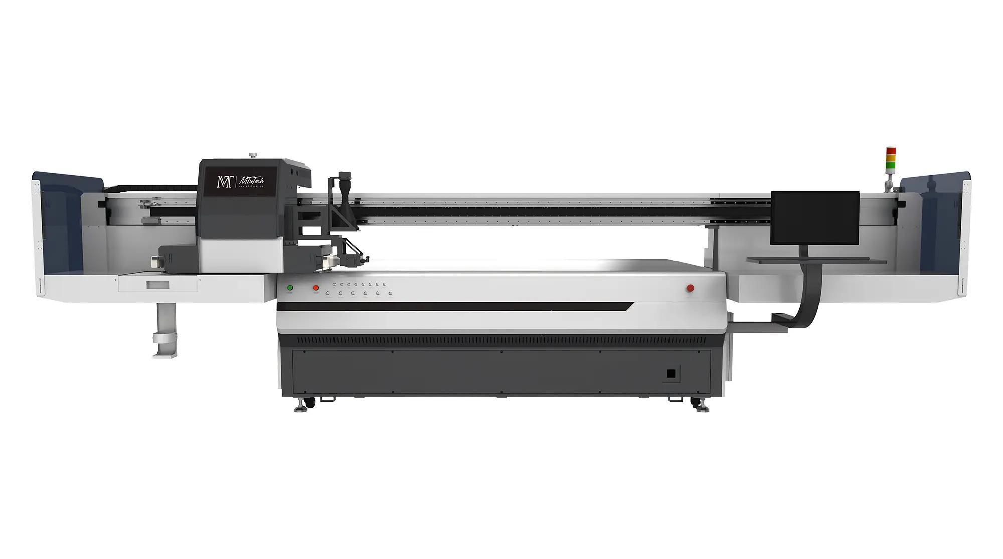
For larger rigid panels, the vacuum hold-down system can help keep the substrate in place during printing. MTuTech's MT-UV 2513Pro flatbed UV printer has features as visual positioning technology, camera-based contour recognition, and a vacuum system. Buyers should confirm that the selected configuration supports the specific pre-cut panel workflow they need.
For mixed-SKU production, keep the print file, panel drawing, registration setup, and inspection record linked to the same job identifier. This reduces the risk of using the correct artwork with the wrong panel size or cutout layout.
Inspect Cutout Alignment and Edge Margins After Printing
Post-print inspection verifies that the physical result meets the drawing and appearance requirements. Camera registration helps establish the print position, but final inspection remains necessary to confirm that the complete process is working correctly.
A practical inspection plan should cover several areas.
· Position accuracy: Compare printed reference points with the intended positions relative to holes, slots, and outer edges.
· Edge clearance: Measure the actual distance between printed elements and the relevant panel boundaries. Compare the measurements with the approved drawing or tolerance specification.
· Layer alignment: If the design uses white ink, CMYK, or varnish layers, inspect for visible offsets, halos, or unintended gaps.
· Surface quality: Check for dust, smearing, scratches, or other defects that could affect the finished panel.
· Repeatability: Compare multiple pieces from the same batch to identify systematic shifts or inconsistent margins.
When an error occurs, identify whether it originates from the cut part, artwork, camera recognition, panel placement, or print setup. Changing the registration settings without identifying the source can introduce new errors or conceal a problem in the cutting file.
For OEM production, retain the approved sample, final artwork version, panel drawing, inspection measurements, and relevant machine settings. These records provide a practical reference when repeat orders arrive or a supplier changes the acrylic material or cutting process.